Let's figure out what the transformation coefficient is. Essentially this is a technical quantity. It's all about the following. In order to account for the electricity consumed by a large facility (such as a residential high-rise building), it becomes necessary to use specialized equipment that reduces the voltage power transmitted to the contacts of a common building meter.
These metering devices are not connected directly to the electrical network of the house, due to the impossibility of connecting high voltage power through a traditional direct-connection meter (they do not work with high currents).
In order to prevent failure of the meter, it is necessary to reduce the power of the supplied voltage.
Transformers are used for these purposes; they are selected based on the required load level.
The transformation ratio of the electricity meter varies depending on the installed equipment. Thus, an electricity meter working in conjunction with a transformer reads a load reduced by 30, 40 or 60 times. Simply put, these numbers represent transformation ratios.
What is transformation ratio?
In order to account for electrical energy that is consumed by large objects, including residential multi-story buildings, specialized equipment is used that helps reduce the voltage power indicators that are transmitted to the contacts of a common building meter.
Such electric meters do not have a direct connection to the electrical network at home, which is due to the inability to connect high voltage using traditional direct-connection devices.
Thus, in order to prevent damage to meters, it is necessary to reduce the power ratings for the supplied voltage using transformer standard equipment. The choice of such equipment is directly influenced by the level of required load.
The transformation coefficient of electrical energy metering devices may vary depending on the characteristics of the installed equipment. As a result, meters for measuring electricity costs, operating with transformers, record the load, which is reduced by several tens of times.
The data obtained by the metering device is the transformation coefficient, and in order to determine the real electricity consumption, you will need to multiply the readings of the electric meter by the CT.
Schemes for connecting the meter via current transformers
For correct metering of electricity using CTs, it is necessary to observe the polarity of connecting their windings: the beginning and end of the primary are designated L1 and L2, the secondary - I1 and I2.
Schemes for semi-indirect connection of three-phase electric meters (using only CTs) can be made in different versions:
Seven-wire. This is an outdated and least preferred scheme in terms of electrical safety due to the presence of a connection between current and measuring circuits - the current circuits of the electric meter are energized.
Ten-wire circuit. More preferred and recommended for current use. The absence of a galvanic connection between the current circuits of the meter and voltage circuits makes connecting the meter safer.
Connection diagram for an electric meter through a test block. According to the requirements of PUE clause 1.5.23, it should be used when connecting a model meter through a CT. The presence of a test box allows for shunting, disconnecting current circuits, connecting a meter without disconnecting the load, and phase-by-phase voltage removal from the measured circuits.
The connection is made on the basis of a ten-wire circuit; its difference from the latter is the presence of a special test adapter block between the electric meter and the CT.
With CT connection in a “star”. Some terminals of the secondary windings of the CT are connected at one point, forming a “star” connection, others - with the current coils of the meter, also connected according to the “star” circuit.
The disadvantage of this method of connecting metering is the great complexity of switching and checking the correct assembly of the circuit.
How to determine the transformation ratio: formula
The transformation ratio of an electricity meter indicates how many times the input parameters of voltage or current differ to a lesser or greater extent from the output parameters.
For indicators exceeding one, a decrease is made, and, conversely, for indicators less than one, a device of an increasing type is used.
Transformation ratios for voltage or current differ.
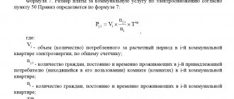
Calculation formula: k=U1/U2=N1/N2 ≈ I2/I 1, where:
- U1 and U2 – difference in electrical voltage on the primary and secondary windings;
- N1 and N2 – number of turns of the primary and secondary windings;
- I2 and I1 – indicators of current strength in the primary and secondary windings;
- k – required CT parameters.
As a rule, such parameters of the transformation ratio are necessarily indicated in the accompanying documentation that comes with the equipment. You can also find out this information from the markings on the body of such a device.
A difficult situation is when the CT needs to be calculated independently, according to data obtained empirically. In this case, current is passed through the primary winding of the equipment and a short circuit is made on the secondary winding, after which the amount of electric current passing through the secondary winding is measured.
Independent calculation involves dividing the value of the primary current by the value of the secondary winding. The result of such calculations is a quotient represented by the transformation coefficient.
Main parameter of the transformer
The main characteristic of any transformer is the transformation ratio. It is defined as the ratio of the number of turns in the primary winding to the number of turns in the secondary winding. In addition, this value can be calculated by dividing the corresponding EMF indicators in the windings.
Formula
In the presence of ideal conditions, when there are no electrical losses, the solution to the question of how to determine the coefficient is carried out using the ratio of the voltages at the terminals of each winding. If the transformer has more than two windings, this value is calculated for each winding in turn.
In step-down transformers, the transformation ratio will be above unity; in step-up devices, this indicator ranges from 0 to 1. In fact, this indicator determines how many times the voltage transformer reduces the supplied voltage. It can be used to determine the correct number of turns. This coefficient is determined on all available phases and on each branch of the network. The data obtained is used for calculations, making it possible to identify wire breaks in the windings and determine the polarity of each of them.
You can determine the real transformation ratio of the transformer current using two voltmeters. In transformers with three windings, measurements are made on at least two pairs of windings with the lowest short-circuit current. If some elements of the transformer and branches are covered with a casing, then determining the coefficient becomes possible only for the terminals of the windings brought out.
In single-phase transformers, to calculate the operating transformation ratio, a special formula is used in which the voltage supplied to the primary circuit is divided by the simultaneously measured voltage in the secondary circuit. To do this, you need to know in advance how each indicator is measured.
It is prohibited to connect voltage to the windings significantly higher or lower than the rated value specified in the transformer passport. This will lead to an increase in measurement errors due to losses of current consumed by the measuring device to which the three-phase transformer is connected. In addition, the measurement accuracy is affected by the no-load current. For most devices, a special table has been developed, which contains fairly accurate data that can be used in calculations.
Measurements should be carried out with voltmeters with an accuracy class of 0.2-0.5. A simpler and faster determination of the coefficient is possible with the help of special universal devices that make it possible to do without the use of extraneous AC voltage sources.
Estimated accounting factor
To clarify the real level of electrical energy consumption, it is necessary to take readings from the electric meter, and then multiply them by CT.
In practice, the CT of a transformer that reduces voltage at home is 20 units, so the data from the meter must be multiplied by this figure, as a result of which the actual electrical energy consumption will be obtained.
How to take readings from three-phase meters
To figure out how to take readings from three-phase electricity meters, you need to know which meter is used:
- old type with transformers;
- electronic without transformers, the so-called direct connection meter.
Electronic ones are easy to use: information is displayed on the display, just like in conventional single-phase devices. Readings are taken in the same way.
Watch this video on YouTube
In old PUs, the phases are connected via transformers. To correctly transmit data on energy consumption, transformation ratios are required. Actual consumption is calculated using the formula:
kWh (according to meter readings) * k (transfer coefficient)
The procedure for calculating consumption is specified in the contract with the energy supply company. Perhaps the documents indicate the required coefficient values. In some cases, the supplier undertakes the calculation, and the consumer provides only actual readings.
The correctness of the transmitted meter readings guarantees correct charges and no risk of significant overpayment for the supplied resource.
Types of electricity metering devices
Meters are multifunctional devices for recording consumption, as well as storing information on electrical energy consumption. Today, three versions of metering devices are in use, designed to account for consumed electrical energy. These include induction, electronic and hybrid models. The last option is the least common.
Mechanical or induction metering devices
Devices of this type consist of two coils.
The first voltage coil limits the parameters of alternating current, blocking interference and forming, in accordance with the voltage, a special magnetic flux.
The second current coil produces an alternating current.
The advantages of mechanical models include high reliability and structural simplicity, long service life, independence from voltage surges and affordable cost. When choosing induction devices, you need to take into account the fairly large dimensions of the device.
Despite its widespread use, such equipment belongs to devices of a low accuracy class and is characterized by increased energy consumption, and the errors in the received data are especially noticeable under conditions of low network load.
Electronic meters
The range of electronic devices is distinguished by a fairly high cost, which is fully justified by the decent quality of the device, including a higher accuracy class and the ability to function in multi-tariff mode.
The principle of operation is based on the method of converting input analog signals into a special digital code, decrypted using a microcontroller.
Single-phase multifunctional electronic electricity meter DDS28U
The decrypted data goes to the display or the so-called optical port. In addition to high accuracy and a multi-tariff system of use, the advantages include the ability to conduct energy metering in two directions, data storage, the ability to obtain readings remotely, as well as durability and compact dimensions.
When choosing, you need to take into account the main disadvantages of such models, which are high sensitivity to voltage drops and lack of maintainability.
Hybrid meters
Today, hybrid metering devices are used extremely rarely by consumers. This intermediate version of the electric energy meter has a digital interface, and the measuring part of the device can be of the induction or electronic type. Characteristic is the presence of a mechanical computing device.
Connection diagrams
Electrical meters and transformers are connected taking into account safety requirements and operating rules, as well as the characteristics of the device itself. The minimum installation temperature is +5˚ Celsius. Otherwise, a correct technical connection will not work - devices that operate with voltage and current do not tolerate low temperatures well.
If you need to connect a transformer outdoors during the cold season, you need to build a special cabinet - insulated and sealed. The device itself is usually installed at a height of 1-1.7 meters.
Installation of a meter with current transformers
It is not always possible to measure consumed electricity through a meter connected directly to the power supply (to an outlet). In circuits with a voltage of 380 Volts and current limits greater than 100A - accordingly, consumption increases to 60 kW - installation of a measuring current transformer is required. Masters call such a connection indirect, but this method provides the most accurate data. In addition, there are two more methods:
The first is used in industrial enterprises and large factories with a power consumption above 0.4 kW and a current of more than 100A.
The “star” scheme, in turn, can be complete or incomplete. For a full star, devices with uniform load distribution and symmetrical current flow are suitable. The transformer is installed on all phases, and the relay winding is connected in a star shape.
Incomplete - two-phase two-relay circuit with the formation of a star part. This circuit quickly responds to short circuits (except for grounding), and it is also possible to install it on interphase panels.
Installation of a multi-turn meter
A three-phase transformer connection meter is used in multi-wire networks. For multi-turn connections, the primary winding of the coil is replaced with a cable one. The device controls the movement of current through the secondary winding. Otherwise, the transformer works on the same principle as other types of equipment.
Ten-wire circuit
This connection method is suitable for use in powerful power circuits, the operation of which is provided by transformers. Galvanic type isolation is suitable for industrial and domestic needs and guarantees the safe operation of the equipment. Connection sequence by terminals (from first to last):
- phase, input (A);
- phase mechanism measuring circuit, input;
- measuring drive, output (A);
- terminal, phase, input;
- phase mechanism measuring circuit, output (B);
- phase, output (B);
- phase, input (C);
- circuit, phase measurement - input.
Seven-wire circuit
This connection scheme has a number of advantages and some disadvantages. Slightly different from ten-wire. It is convenient to work with the meter - there is no need to completely turn off the system when working with the panel, metering devices and transformers.
Thanks to grounded current circuits, dangerous potential does not accumulate at the outputs of the secondary windings, which often leads to short circuits and equipment burnout. A test box is connected to the general network, which allows you to safely disconnect the power circuits.
The seven-wire method is one of the outdated ones and is rarely used. Electrical installers from professional companies do not recommend connecting using more modern methods.
Scheme with combined circuits
This scheme differs significantly from the previous ones. Current transformers with combined circuits are connected through special jumpers (the path is from L1 to L2).
Other connection systems
In addition to those indicated, there are other schemes for connecting the meter to the transformer. The use of a test block in a connection - in accordance with clause 1.5.23 of the Electrical Installation Rules - is necessary when activating a model meter. This is additional equipment that allows you to bypass and disconnect current circuits, activate meters without reducing the voltage load. Another point is the possibility of taking readings in phases.
The basis of the connection through the test box is a ten-wire circuit. The difference lies in the installation between the metering device and the transformer structure of the transition block with the necessary protective and distribution functions.
Tips and tricks
Today, in multi-apartment residential buildings and the private country sector of households, single-phase electrical energy meters are mainly installed, which are designed for a standard voltage of 220 V.
However, when using a large number of household appliances with different power ratings, it is recommended to give preference to three-phase meters, which allows you to connect energy-intensive devices that are designed for voltages of 220 V and 380 V.
When choosing a device, you must pay attention to the calculated current indicators, as well as the accuracy class, represented by the largest permissible relative error, expressed as a percentage.
All newly installed three-phase meters must have state verification seals that are not older than twelve months. The seal on a single-phase meter must not be older than two years.
Electronic or induction
Experts in the field of electrical engineering note that today consumers prefer electronic types of reading devices, since their accuracy class is lower than that of induction devices.
The meter's transformation ratio affects the accuracy of the final readings. On average, induction samples have an accuracy class of 2.5, while electronic samples have an accuracy class of 2.0. This means that the reading error as a result of the operation of an electronic-type electrical reading device is up to 2%, and for an induction one - 2.5%. It is for this reason that electronic equipment is now more often installed, since it allows you to save more by getting more accurate readings. Experts strongly do not recommend installing equipment with an overestimated transformation ratio. In modern electrical engineering, it is customary to use transformers with a static CT, which is guaranteed not to change during operation.
Such electric meters include Mercury-230. Mercury-230 is produced in Russia and is considered one of the best samples for commercial and private use. Mercury-230 can be manufactured for single- and double-tariff plans. Typically, the Mercury-230 model supports a three-phase electrical network. On average, the warranty period for Mercury-230 is 25 years, which is the optimal choice when taking into account quality and price. Mercury-230 fully complies with GOST standards.
Mercury-230 has a good accuracy class and operates stably under significant changes in ambient temperature throughout the entire life of the device. Mercury-230 allows you to accurately measure the current parameters of the electrical network - frequency, power factor, current value of phase current, voltage.
Tariffizer Mercury-230 allows you to simultaneously take into account readings at 4 tariffs in 16 time zones of the day, as well as for four types of days. Mercury-230 can take into account forward active electricity and its total power by phase, the sum of the phase values with determining the direction of the total power vector.
Classification
Electricity meters are divided into single-phase or multiphase; such devices are used for networks where there may be alternating voltage.
For example, a single-phase meter, which is installed in almost all residential premises, functions only in the range from 220 to 230 V, while three-phase ones also measure voltage in the range from 220 to 400 V.
Detailed meter classification scheme Many energy companies provide the opportunity to save on electricity by installing a multi-tariff meter. Such devices have two or more independent scales, the transition between them is carried out at a certain time.
Typically, at night, 1 kW of electricity is much cheaper, but the volume of its consumption is also greatly reduced. To save money, you can program some devices, such as a washing machine or dishwasher, to operate at night.
There are 3 types of counters:
- induction;
- electronic;
- contactless.
Connection diagrams
Connecting the measuring transformer to the meter can be done in different ways. It is prohibited to use current transformers with metering devices intended for direct connection to the electrical network. In such cases, the possibility of such a connection is first studied, and the most suitable transformer is selected in accordance with the individual electrical circuit.
If instrument transformers have different transformation ratios, they should not be connected to the same meter.
Before connecting, you must carefully study the layout of the contacts on the three-phase meter. The general principle of operation of electric meters is the same, therefore the contact terminals are located in the same places in all devices. Contact K1 corresponds to the power supply of the transformer circuit, K2 is the connection to the voltage circuit, K3 is the output contact connected to the transformer. In the same way, phase “B” is connected through contacts K4, K5 and K6, as well as phase “C” with contacts K7, K8, K9. Contact K10 is zero; the voltage windings located inside the meter are connected to it.
Most often, the simplest scheme for separate connection of secondary current circuits is used. A phase current is supplied to the phase terminal from the network input circuit breaker. For ease of installation, the second terminal of the phase voltage coil on the meter is connected from the same contact.
The phase output is the end of the primary winding of the transformer. Its connection is made to the load of the distribution board. The beginning of the secondary winding of the transformer is connected to the first contact of the current winding of the meter phase. The end of the secondary winding of the transformer is connected to the end of the current winding of the meter. The remaining phases are connected in the same way.
In accordance with the rules, the secondary windings are connected and grounded in the form of a full star. However, this requirement is not reflected in every electric meter passport. Therefore, during commissioning, it is sometimes necessary to disconnect the grounding loop. All installation work must be carried out in strict accordance with the approved project.
There is another scheme for connecting a three-phase meter through current transformers. used very rarely. This circuit uses combined current and voltage circuits. There is a large error in the readings. In addition, with such a scheme it is impossible to timely detect a winding breakdown in the transformer.
The correct choice of transformer is of great importance. The maximum load requires a current in the secondary circuit of at least 40% of the nominal value, and the minimum load requires 5%. All phases must alternate in the prescribed order and be checked with a special device - a phase meter.
Commercial losses: the main direction of increasing efficiency in the electric power industry
Commercial losses of electricity are considered a difficult value to predict, since they depend on consumers and their desire to deceive the enterprise or the state. The basis of these problems are:
- Seasonal component. The presented concept includes the underpayment of individuals for actually supplied electrical energy. For example, in the Republic of Belarus, there are 2 reasons for the appearance of the “season” - the availability of tariff benefits and payment not on the 1st, but on the 25th.
- Imperfection of metering devices and their incorrect operation. Modern technical means for determining consumed energy have greatly simplified the task for the subscriber service. But electronics or an incorrectly adjusted accounting system can fail, which causes an increase in commercial losses.
- Theft, underestimation of meter readings by commercial organizations. This is a separate topic for conversation, which involves various tricks of individuals and legal entities to reduce electrical energy costs. All this affects the growth of losses.
Operating principle of instrument transformers
The operating principle of these devices is quite simple. The primary winding of the transformer, connected in series, carries the phase load current. Due to this, electromagnetic induction occurs, creating a current in the secondary winding of the device. The current coil of a three-phase electric meter is connected to the same winding.
Depending on the transformation ratio, the current in the secondary circuit will be significantly less than the phase load current. It is this current that ensures the normal operation of the meter, and the readings are multiplied by the value of the transformation ratio.
Thus, current transformers or instrument transformers convert the high primary load current into a safe value suitable for measurement. Current transformers for electric meters operate normally at an operating frequency of 50 Hz and a secondary current rating of 5 amperes. Therefore, if the transformation ratio is 100/5, this means a maximum load of 100 amperes, and the value of the measuring current is 5 amperes. Therefore, in this case, the readings of the three-phase meter are multiplied by 20 times (100/5). Thanks to this design solution, there was no need to manufacture more powerful metering devices. In addition, the meter is reliably protected from short circuits and overloads, since a burnt-out transformer is much easier to replace than installing a new meter.
There are certain disadvantages with this connection. First of all, the measuring current in the case of low consumption may be less than the starting current of the meter. Therefore, the meter will not work and give readings. First of all, this applies to induction-type meters with very large own consumption. Modern electricity meters practically do not have such a drawback.
When connecting, special attention must be paid to maintaining polarity. The primary coil has input terminals
One of them is intended for connecting a phase and is designated L1. Another output - L2 is needed to connect to the load. The measuring winding also has terminals, designated respectively as I1 and I2. The cable connected to outputs L1 and L2 is designed for the required load.
For secondary circuits, a conductor is used, the cross-section of which must be at least 2.5 mm2. It is recommended to use multi-colored wires with marked terminals. Often, the secondary winding is connected to the meter using a sealed intermediate terminal block. The use of a terminal block allows you to replace and maintain the meter without cutting off the electricity supplied to consumers.
Calculation example
Let's consider how to calculate the readings of an electricity meter with current transformers with a transformation ratio of 100/5=20.
For example, the meter showed a value that was 200 kW higher than the figure written off at the beginning of the period.
When looking for an answer to the question of how to calculate the readings of an indirectly connected electricity meter with current transformers, it is important to take into account that the error between the actual value and that indicated in the technical documentation should not exceed 2%. The reading must be taken from the operating branch.
When deciding how to calculate the readings of an electricity meter connected to a network with a current transformer, it is necessary to take into account that any device has a certain service life. After it has ended, you should not hope that the readings read will be accurate.
When purchasing a converter, you must check the year and month of manufacture. This equipment is inspected every 4 years so it should not be out of date.
The data on the product nameplate must completely match the information in the data sheet.
When choosing a three-phase CT, it is necessary to take into account that the period from the date of issue to sealing should not exceed 12 months. Otherwise, there will be additional costs for the purchase of another converter or government inspection of the one already purchased.