Drawing up a topographic plan is an integral part of any construction or improvement on a land plot. Of course, you can put a shed on your property without it. Lay out paths and plant trees too. However, starting more complex and voluminous work without a topographic plan is undesirable and often impossible. In this article we will talk specifically about the document itself, as such - why it is needed, what it looks like, etc.
After reading, you need to understand for yourself whether you really need a topographic plan, and if so, what it is.⇓
What is a topographical plan of a land plot?
We won’t burden you with the official definition, which is needed more for professionals (although they already know the essence). The main thing is to understand the essence of this plan and how it differs from others (for example, a floor plan, a situational plan, etc.). To compile it, it is necessary to conduct a topographic survey. So, a topoplan is a drawing of the elements of the situation, terrain and other objects with their metric and technical characteristics, made in approved symbols. The main feature is its high-altitude component. That is, anywhere on the topographic plan you can determine the height of the object depicted there. In addition to height, on a topoplan you can measure the coordinates and linear dimensions of objects, taking into account the scale, of course. All this data can be obtained either from a paper copy or from a digital one. Usually both options are prepared. Therefore, the topographic plan, in addition to a visual representation of the area, is the starting point for design and modeling. A topoplan is also often called a geobase and vice versa. Essentially these are two identical concepts with minor reservations. The geobase may contain several topographic plans. That is, this is a collective concept for the entire territory of the object under study. Underground communications must be indicated on the geobasis, in contrast to the topoplan (where the underground is indicated if necessary). But despite the subtleties, these concepts can still be equated.
Types of topoplans by content
Topographical diagrams of land plots differ in content and are divided into basic and specialized:
- Basic. This category includes general geographical engineering schemes that are used in economic sectors. The maps use 700 captions and designations of object characteristics and 400 symbols. In this case, 4 colors are used.
- Specialized. The plan is developed for a specific task. On specialized plans, additional information is printed along with the standard information for the topoplan. Such diagrams may underestimate or overestimate the accuracy of the depiction of the relief of the contour of the site and map elements. If necessary, specialized plans use an unconventional relief section, excluding some elements that are integral to the standard plan.
Both types of topoplans of land plots must comply with the technical requirements of departmental instructions.
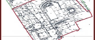
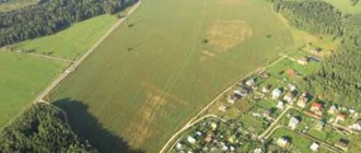
Example of aerial photography of a site
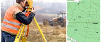
Who draws up and what is used to make a topographic plan?
Topographical plans are drawn up by surveying engineers. However, now you can’t just graduate from university, get a diploma, buy equipment and start doing topographic surveys. It is also necessary to work as part of an organization that has membership in the relevant SRO (self-regulated organization). This has become mandatory since 2009 and is intended to increase the responsibility and preparedness of surveying engineers. Our company has all the necessary certificates permitting engineering survey activities. We use advanced equipment (our devices) to successfully work in any conditions and areas of geodetic surveys. In particular, electronic total stations, digital optical levels, satellite equipment, electronic tape measures, etc. All devices have been certified and have certificates of passing metrological verification. All materials and measurements are processed using specialized licensed software.
What tools are used for geodetic surveys
The most classic instrument used by surveyors is the total station . During field work, this item is indispensable.
The tool performs many tasks: measures angles, heights, lengths of objects. The operating principle is based on optical-electronic measurement of the indicated parameters. The versatility and functionality allows the device to perform most geodetic work.
Another device necessary for surveying a site is a level . It is used at road construction sites to control the vertical laying of road materials. The device allows you to accurately determine the excess of one object over another, their level and height. Different types of levels differ from each other in their operating principles. Optical, laser and auto-installation levels are known.
The pole allows you to ensure correct measurements . This instrument resembles a rounded stick approximately 2 meters high with a reflector at the top of the instrument that returns the level or total station signal back to the measuring instrument.
To achieve precise measurement goals, satellite signals obtained using GPS equipment are widely used.
A tripod, or tripod, fixes geodetic measuring instruments in a stationary state . Before the instrument is secured to the tripod, a tribrach is installed - a device that holds the instrument in a horizontal position above the fulcrum. Tripods are made of metal, wood or composite materials.
A pipe and cable detector is necessary for surveyors to search for utilities at a study site . The device comes with a generator that creates sound vibrations on the visible part of the pipeline. This is how the path of the underground part of communications is calculated with an accuracy of 5 cm.
Why is a topographic plan needed?
Why does an ordinary land owner or a large construction organization need a topoplan? In essence, this document is a pre-design document for any construction. A topographic plan of a land plot is needed in the following cases:
- to obtain a building permit
- for designing work during the construction and reconstruction of buildings and structures. This also includes the design of communications for subsequent connection to consumers (electricity, gas, water supply, sewerage, heating networks, etc.) or their reconstruction
- for registration of ownership or lease of a newly formed land plot (when drawing up a diagram of the location of a land plot on the KPT)
- for landscape design on a land plot (large-scale detailed topoplans)
- for vertical planning of the territory
- for coordination with Rosnedra of the planned construction
We have written a full article on this topic - if interested, click here.
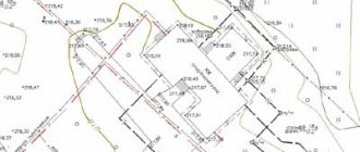
Difference from topographic map
A topographic plan differs from a map in the type of projections. Maps are constructed in the transverse cylindrical projection of K. Gaus without distortion of angles and distortion of lengths along the edge of the zone 1 to 1000. Small areas of terrain are recorded on the plans, so the spherical distortion used in drawing up maps is not applied to them.
Topoplans use an orthogonal projection. Images of objects on paper correspond to how real objects appear in the horizontal plane.
A map is an image of the entire or partial earth's surface that conveys the natural spherical distortion of the earth. Image distortion occurs due to map projection.
Example topographic map
Documents required for ordering a topographic plan
If the Customer is an individual, it is enough to simply indicate the location of the object (address or cadastral number of the site) and verbally explain the purpose of the work. This will not be enough for legal entities. Still, interaction with a legal entity implies the mandatory drawing up of an agreement, an acceptance certificate and receipt of the following documents from the Customer:
- Terms of reference for topographic and geodetic works
- Situational plan of the facility
- Available data on previously completed topographic work, or other documents containing cartographic data about the object
Ilya Chernyshev
Ask a Question
After receiving all the data, our specialists will immediately begin work.
Why do you need site geodesy?
Geodetic work allows you to take into account all the features of the site and optimally place buildings on them.
The need for geodetic research most often arises in 2 cases: it is necessary to establish the boundaries of the plot and confirm your rights during construction. Carrying out the work makes it easier to solve both problems.
- Geodetic surveying accurately establishes the site area and configuration . Based on the data, land surveying is determined and recorded, that is, the result of geodesy is considered as the basis for making a decision.
- A cadastral survey is necessary to register a plot of land in the cadastral book . If this is not done, the plot cannot be sold or its status changed. In fact, construction on it will also be prohibited.
- Geodetic work allows you to find the best position for a house . The study takes into account landscape features, and a well-chosen location will save the cost of excavation work.
- It is recommended to place buildings, and especially residential ones, in such a way as to form a drainage system for water from the foundation. To do this, the house must be placed on a hill, raised, or drainage constructed. Topographic surveys help calculate the volume of drainage and excavation work and develop the correct scheme.
- When arranging the landscape, you need to take into account the relief . Geo-surveying will provide the owner with the most accurate information about him.
- When building a house, a competent builder carries out the axes of the building, determines the zero mark, and the geometry of the building structures . This is impossible to do without accurate knowledge of the terrain. One of the signs of professionalism of a construction company: mandatory geodetic survey.
The use of geodetic survey results during construction is a guarantee of long-term operation.
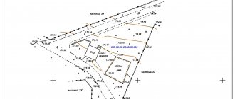
What is shown on the topographic plan?
It should be understood that topographic plans include scales from 1:10000 to 1:100.
Accordingly, the objects displayed on them are different. After all, it is impossible to display trees or communications on a small scale; everything will merge into one abstract spot. There is a rule for generalizing displayed objects. The smaller the scale, the more significant and large objects are included in the plans. The most popular and common scales of plans are 1:500 and 1:1000. They are used for design during construction. Therefore, let's talk about the objects and symbols present on large-scale topoplans. First of all, the topoplan is divided into the drawing itself and other auxiliary images. Supporting data include:
- mathematical basis . These are images of crosses and the designation of their coordinates. Thus, the drawing is rigidly tied to the coordinates on the ground.
- symbols . If any symbols are used on the topographic plan that do not correspond to generally accepted symbols, they are indicated on the drawing. The remaining symbols used on the plan cannot be deciphered or explained.
- main stamp . All additional information about the drawing (object address, scale, artist, etc.) can be found here.
The graphic part of the drawing displays the following data:
- relief. It is depicted by basic and thickened horizontal lines. In addition to them, the height of the area can be judged by elevation marks. They are indicated in the format “123.45” in meters above sea level. The Baltic height system is generally accepted in Russia, but in Moscow the Moscow system is adopted. It differs slightly from the Baltic (+92 mm). Based on marks and contour lines, one can judge the terrain and identify mountains, pits, ridges, hollows, saddles and other elements.
- soils and vegetation. On the topoplan, the type of vegetation or soil must be indicated in symbols if there is no vegetation.
- hydrography. Hydrography includes water bodies such as rivers, streams, lakes, swamps, etc. The name (if any), flow direction, speed, depth are indicated.
- road network. These are automobile, railway, tram, and pedestrian routes. The coating or width of the rails is indicated.
- network engineering . Ground and underground communications such as power lines, gas, water supply, sewerage, communication cables, etc.
- fencing . Accordingly, all types of fences, hedges, etc.
- buildings and constructions . All buildings and structures have signatures with characteristics of number of storeys, material and belonging to residential buildings.
- borders _ The topoplan indicates the boundaries of settlements, survey boundaries and often cadastral boundaries of land plots.
Analysis of the obtained measurements.
After collecting all the data about the site, we begin to analyze it.
Let's start with an altitude analysis - draw horizontal lines on the site plan. To do this, we look for points on the plan with the same height and connect them with a smooth line. But there will be few such points, and maybe there won’t be any at all. How to set the altitude? To do this, we use the interpolation method, i.e. We will find intermediate values of quantities from the available discrete set of known values. If we know the height values at two neighboring points, then we can assume how the altitude of the area changes between them. We place a point with the desired height value proportional to the distance between two neighboring points.
We use arrows on the plan to mark the direction of water flow.
Let's analyze the wind and solar zones. For clarity, it is better to use colored pencils or markers. For example, if you take blue and red markers, where blue is windless areas, red is sunny places. When superimposed on each other, a purple color is obtained, indicating that there is a quiet, windless, sunny area here. We get the most favorable places for vegetation and recreation areas.
Place all existing communications on the plan.
Thus, we analyzed the data obtained and built a topoplan, which will be very useful to us for the further design of the Family Estate. If you have any questions or want to discuss something, be sure to leave a comment.
Documents regulating the design and preparation of a topoplan
When drawing up a topoplan, you should adhere to the application of those topographic symbols that are on the list compiled by the Central Research Institute of Geodesy, Aerial Photography and Cartography of the GUGK and approved by the GUGK under the Council of Ministers of the USSR on November 25, 1986.
To this day they have survived without significant changes and are used everywhere in the design of topoplans. Although Mosgorgeotrest, when submitting topographic plans to the geofund, requires slightly different signs established by this organization. As for the regulatory documents on the methods of conducting topographic surveys and drawing up topographic plans, rather “ancient” SNIPs and GOSTs are also used. Using the buttons below you can download: CONVENTIONAL SIGNS FOR TOPOGRAPHIC PLANS scales 1:5000,1:2000,1:1000,1:500
SP 47.13330.2012 “ENGINEERING SURVEYS FOR CONSTRUCTION. BASIC POINTS
SP 11-104-97 “ENGINEERING AND GEODESIC SURVEYS FOR CONSTRUCTION”
GOST R 51872-2002 “EXECUTIVE GEODESIC DOCUMENTATION”
Accuracy of topographic plans
The above regulatory documents specify in detail the tolerances for determining the horizontal and altitude coordinates of the position of objects on topoplans. But in order not to delve into a large amount of technical and often unnecessary information, we will present the main accuracy parameters for topographic plans at a scale of 1:500 (as the most popular). The accuracy of a topoplan is not a single and inviolable quantity. You cannot simply say that the angle of the fence is determined with an accuracy of, for example, 0.2 m. It is necessary to indicate regarding what. And here the following quantities appear.
- the average error in the planned position of clear contours of objects should not exceed 0.25 m (undeveloped area) and 0.35 m (built-up area) from the nearest points of the geodetic basis (GG). That is, this is not an absolute value; it consists of errors in the shooting process and errors in starting points. But in essence it is an absolute error in determining a terrain point. After all, starting points are considered infallible when leveling topographic moves.
- the maximum error in the relative position of points of clear contours spaced from each other at a distance of up to 50 meters should not exceed 0.2 m. This is a control of the relative error in the location of terrain points.
- the average error in the planned position of underground communications (identified by a pipe-cable detector) should not exceed 0.35 m from the GGS points.
- the average error in the altitude position of a point relative to GGS points should not exceed 0.125 m in flat areas and 0.16 m at surface inclination angles of more than 2 degrees.
That is, returning to the question of absolute accuracy for most objects in Moscow and the Moscow region for built-up areas, the error in the position of clear objects (buildings, pillars, corners of fences, etc.) does not exceed 0.35 m in plan and 0.12 m in height. This is assuming that the starting points of the GGS have absolutely correct coordinates.
Carrying out geodetic work with your own hands
If you need a simple site plan showing existing buildings for landscaping, then in order to save your budget, you can do geodetic work yourself. Using these measurement results, you can create a design project for your site. Of course, geodetic work performed by specialists will be more accurate compared to independent measurements. The results of geodetic work performed by specialists can be used to prepare official documents.
Tools and accessories
To perform geodetic work with your own hands, you will need the following tools and devices:
- Form B6 cadastral passport (if you have one);
- graph paper;
- protractor, compass;
- compass;
- wooden pegs 1.2 - 1.5 m high;
- hydraulic level or building level;
- rope;
- flat board;
- sledgehammer or hammer.
Determining the boundaries of the site
To carry out topography with your own hands, Form B6 of the cadastral passport can help you. It indicates the exact dimensions of the site, its coordinates, as well as the angles of rotation of the site boundaries. This information can be used as the basis for constructing a simple site plan.
If you have a cadastral plan , then it is better to first transfer it to your plan at the scale you need. And then, according to this plan, transfer it to the area.
If you do not have a cadastral plan , but you know the boundaries of your plot, then first we mark the boundaries of the plot on the ground, and then transfer them to our plan.
The plan can be drawn up electronically or drawn on paper. If you are drawing up a plan on paper, then it is better to use graph paper for these purposes.
Our plan needs to be oriented according to the cardinal directions. A point on the ground is described by three parameters: X, Y, Z. X and Y determine the position of the point in the plane. The X axis shows the north direction. The Y axis defines the east direction. Z axis – shows the position of the point in height. By connecting points on the XY plane, we get a site plan, and the Z coordinate will allow us to describe the terrain.
The ideal option would be if your plot had a regular rectangle or square, but this happens extremely rarely. As a rule, the areas have an irregular shape. In this regard, difficulties arise with constructing a site plan. So, let's begin to figure out how to properly build a site plan.
On the plan, draw the boundaries of the site taken from the cadastral plan and use them as a basis for further construction. Choose the base side. The base side is the side parallel to which we will make all measurements for the project. In general, it is better to choose the longest side of the site as a basis.
Constructing a site plan with a simple quadrangle shape
If your plot shape is quite simple and has a simple quadrangle, then you can get a large-scale plan of the plot by following these steps:
- We draw the base line AB, placing it parallel to the millimeter grid.
- From vertex A, using a compass, we draw an arc with a radius equal to the length of the front part of section AG.
- Similarly, we outline the arc with a radius corresponding to the length of the back side of the section from vertex B.
- Using a compass, we outline an arc equal to the diagonal of the section from vertex A to B. At the intersection of arcs AB and BV, we obtain point B.
- From point B we draw an arc equal to the length of side VG. At the intersection of arcs AG and VG we obtain point G.
- By connecting points A, B, C and D with segments, we obtain a site on a scale that corresponds to the shape of our site on the ground.
Building a site plan with a complex shape
If you have a site with a complex configuration, then divide it into several simple figures in the shape of a quadrangle or triangle. Do the same steps as described above for each figure. As an example, let’s take the following figure, as shown in the figure. Its shape is quite complex. We will have to divide our site into 2 parts: quadrangle AGDE and triangle ABC. First we will form a quadrilateral as described above, and then a triangle.
- We draw the base line AG, placing it parallel to the millimeter grid.
- From vertex A, using a compass, we draw an arc with a radius equal to the length of the front part of section AE.
- Similarly, we outline the arc with a radius corresponding to the length of the rear side of the section from the top of the main body.
- Using a compass we outline an arc equal to the diagonal of the section from vertex A to D. At the intersection of arcs AD and GD we obtain point D.
- From point D we draw an arc equal to the length of side DE. At the intersection of arcs AE and DE we get point E. We have obtained all the points of our quadrilateral AGDE.
- Let's start identifying the points of the triangle. On the side AG we lay off the segment AB and get point B.
- From point B we draw an arc with a radius equal to segment VB.
- From point A we draw an arc with a radius equal to segment AB. At the intersection of arcs AB and BV we obtain point B.
- By connecting points A, B, C, D, E and E with segments, we obtain a site on a scale that corresponds to the shape of our site on the ground.
To obtain this plan, you can use a protractor instead of a compass. Instead of serif arcs, use a protractor to lay out the corners and set aside the corresponding segments of the sides of the area.
Line the resulting plan into squares with sides corresponding to the grid sizes of your future measurements on the ground. The grid size on the ground is usually 10, 20 or 40 m. This depends on the degree of accuracy required.
Shooting a site on the ground.
It is better to carry out all measurements of the site together.
We determine the location of the site relative to the cardinal points and mark it on the plan.
We assign the perimeter of the site as follows:
- Determine the first base point. This is a point that you can accurately determine on the boundary of the site, preferably located on the baseline. For example, on our site you can take the corner of the yard as this point. We drive in the first peg.
- We try to visually determine the height of the relief at this point relative to the entire area. Mark the horizontal level on the peg. If this point turns out to be low in relation to other points on the site, then we place the mark above the middle of the peg. If it is high, then we place the mark closer to the ground. We will consider this mark to be the zero level. If further measurements are above this mark, they will have a positive value. If – below, then negative.
- We measure the height from the ground to the mark on the peg. We record the resulting measurement on our plan.
- Using a compass, we determine the direction of our site boundary line. We hammer in the next peg at a distance corresponding to the side of the grid square.
- We connect two adjacent pegs with a rope. The rope should be in a taut position without bending and horizontally. We obtain the horizontal line of the rope using a board and a building level. Place a level on the board and level the board horizontally. Our rope should go along the board. We fix the rope on the peg.
- Place a horizontal level on the peg. We measure the distance from the ground to the mark on the peg and record the result on our plan.
After taking measurements along the perimeter, we make a grid of squares throughout the entire area. The sides of the squares are usually taken as 10, 20 or 40 m. The size of the side depends on the features of the relief and the degree of accuracy of its display.
Thus we have a plan indicating the heights. The height of the points can be either positive or negative. A positive value means high ground, a negative value means low land.
It is more convenient to mark the elevation levels of the site, starting from the highest point. If your starting point when starting to set off the perimeter of the site is not the highest point, then it will be more convenient to first set aside the entire perimeter of the site, and then mark the height of the points on the site, starting with the highest.
When marking a new point, each time we evaluate the terrain to neighboring points. If we see any features in the area, we mark them on the plan. To do this, we install additional pegs and additionally measure the level to increase the shooting accuracy. This is the basic principle of topography - you need to describe the terrain with pickets at approximately equal distances, adding pickets in those places where it is necessary to increase the accuracy of the survey.
When taking measurements of the site, it is also necessary to mark all the buildings located on the site. And also note all significant vegetation.
It is necessary to determine the road and path network and mark it on the plan.
You also need to determine wind zones: where the winds blow most often, where the strongest winds come from, where wind calms occur. Mark all this on the plan.
Equally important is observing the sun. It is necessary to note sunny and shadow areas.
Cost of preparing a topographic plan
The price for preparing a topoplan depends quite strongly on the initial conditions and the type of final product. In other words, from the technical specifications. Of course, technical specifications are not prepared for all objects; often an oral description of the task is sufficient. We recommend reading the article about the cost of topographic survey and where it comes from. There you will also find the estimated cost of “standard” objects so that you can navigate our pricing policy. If you don’t have the time or desire to read all this, just call 8 (903) 253-35-84 (Ilya) and voice the task. If this is a typical object, the cost can be found out immediately. If not, we will first need to familiarize ourselves with the terms of reference and the situational plan of the facility.
To prepare a topographic plan for a standard plot (up to 15 acres) will cost from 12 thousand rubles.
Prices for topographic plans